


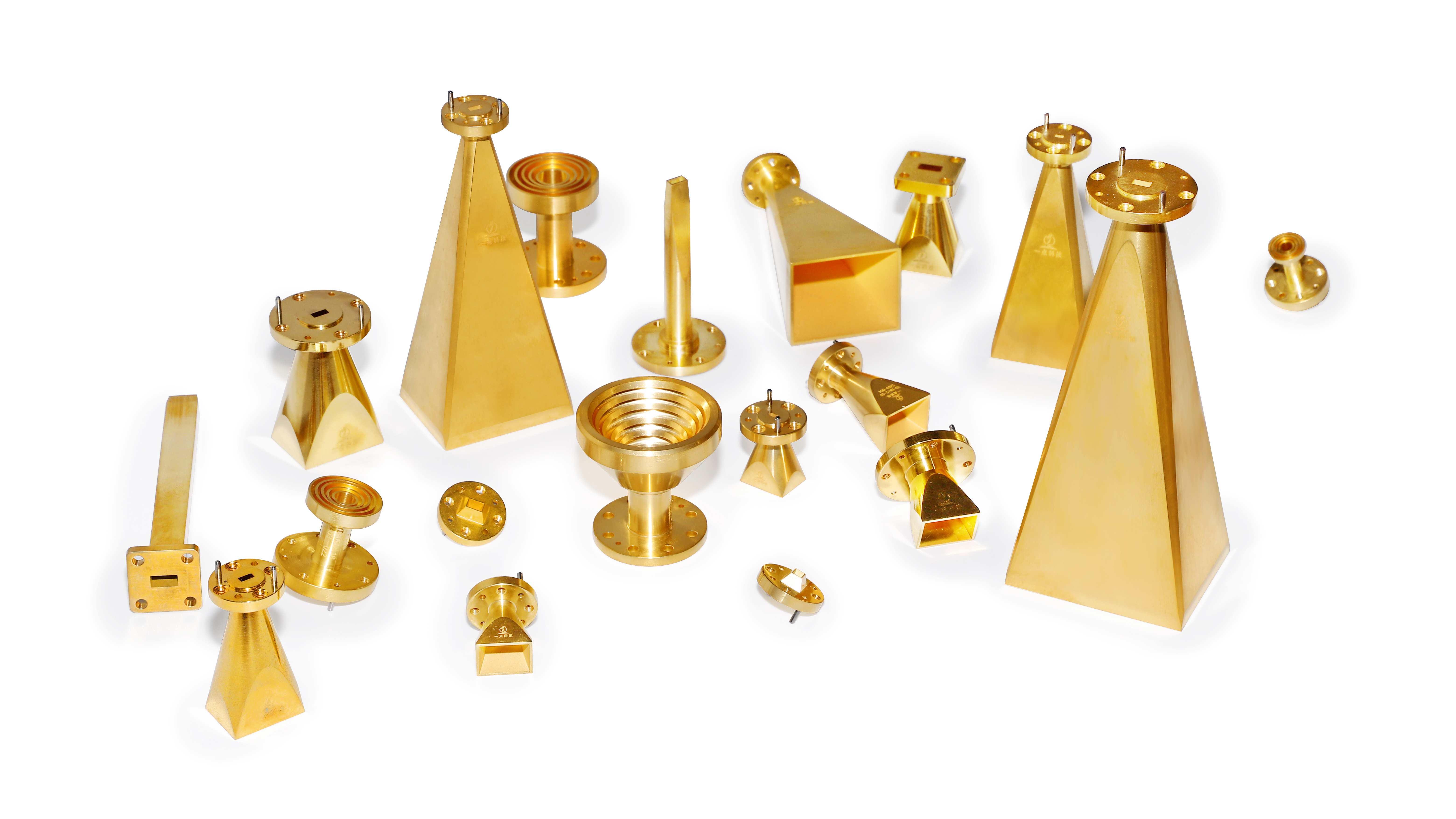
Dedicated to the R&D and manufacturing of microwave and millimeter-wave antennas and passive components.
MORE +
YD-CWH1.5-50
$ 1499
Operating frequency: 500–750 GHz; WR‑1.5 waveguide; 90° H‑plane waveguide bend
Product Category:
Curved waveguide
Keywords:
Product Manual:
- Product Description
- Main Parameters
- Structural parameters
-
The YD-DCWH1.5-50 is an H‑plane bent waveguide with WR1.5 input and output ports. It covers a frequency range of 500 to 750 GHz. Manufactured using precision machining and featuring full gold plating, it ensures excellent electrical performance.Mechanical appearance

High-performance microwave systems demand smooth signal routing without extra attenuation or reflection. Our waveguide bend serves as a core passive component to redirect electromagnetic waves inside waveguide assemblies. We provide both E-plane and H-plane types, built with precise machining to maintain low VSWR and tiny insertion loss. Premium raw materials such as oxygen-free copper and aluminum are adopted, supporting high-power operation under long continuous working cycles. Every unit undergoes strict electrical and dimensional inspection before shipment to avoid signal distortion.
These waveguide bend parts fit diverse application scenarios. They are widely deployed in radar equipment, satellite communication hardware, millimeter-wave test platforms and wireless transmission systems. We supply standard 90-degree models and custom angle solutions according to customer drawings. Different flange types and surface treatment options can be chosen to match existing waveguide pipeline layouts. Compact miter bend styles are also available when installation space is limited.
We deliver flexible manufacturing services for global buyers. Our engineering team reviews project parameters at early stages to optimize structural design. All processing steps follow rigorous quality standards to guarantee consistent batch performance. Whether you need prototype samples or large bulk orders, we arrange production properly to shorten lead times. Contact us now to get detailed technical parameters and competitive quotations for your waveguide system projects
-
Parameters
Minimum value
Typical
Maximum value
Passband frequency
500 gigahertz
750 gigahertz
Voltage Standing Wave Ratio
1.5 ( maximum 1.8)
Waveguide port center distance ( Y To)
50mm
Operating temperature
-40 °C
+85 °C
-
Project
Standardization
Input port
WR 1.5,UG-387/U flange
Output port
WR 1.5,UG-387/U flange
Materials
Copper
Surface Treatment
Gold-plated
Keywords:
Online Consultation
Identifying your needs is the foundation for collaboration and the starting point for our services. Please fill out the requirements form now, and we will contact you promptly.
Top Technology
Recommendation
Product


▪
副标题
Cassegrain antenna
▪
频率最小
200
▪
频率最大
220
▪
极化方式
Linear polarization
▪
典型增益
44
▪
天线端口
WR-04
▪
VSWR
1.5
▪
3dB波束宽度
1

▪
副标题
Gradual方圆
▪
频率最小
22
▪
频率最大
33
▪
VSWR
1.05
▪
波导长度
1.57
▪
过渡类型
Round-to-square transition
▪
波导端口一(min)
∅8.90 round mouth
▪
波导端口二(max)
8.636 × 8.636 square opening

If you are interested in our products, please provide your email address, and we will contact you as soon as possible. Thank you very much.


Copyright © Heilongjiang Top Technology Co., Ltd. Website: 300.CN |Search Engine Optimization|Digital business card | Privacy Policy
Copyright © Heilongjiang Top Technology Co., Ltd
Website:300.cn |Search Engine Optimization